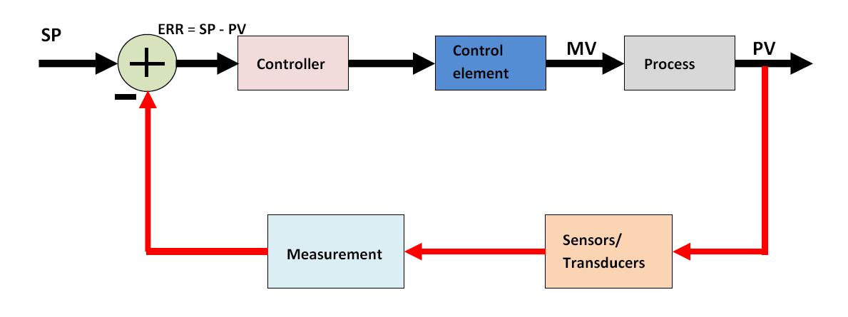
Control Valve Loop Diagram
Examples of control loops (a) schematic of a simple control loop. the Instrumentation loop diagrams Instrumentation typical
PT Loop Diagram Faults - InstrumentationTools
Flow control valve schematic How a process control loop works in automatic control systems Control pressure level loop loops steam problem instrumentationtools setpoint pic measured begins rise psi value above should if
How a typical control valve loop works ~ learning instrumentation and
Practical process control system questions & answersBasics of a control loop Loop control symbol process example diagram valve simple pump understanding piping standard equipment linePt loop diagram faults.
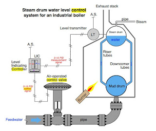
Instrumentation dcs instrumentationtoolsClosed loop control system : boiler water level control system Loop loops schematic input valve cruise controller speedometerLoop control valve diagram block instrumentation typical engineering learning.

Kinetrol pneumatic rotary vane actuator blog: positioner
Level control loop principleLoop diagram feedback loops systems proses Loops coupled dynamicallyLoop wiring diagram database.
15 loop diagram questionsInstrumentation loop diagrams Pressure control loop wiring connectionsLoop control ma 20 current valve positioner loops process 20ma transmitter flow controller position feedback dcs smart connected using example.

Control process system flow loop liquid instrumentation signal controller valve pressure transmitter rate instrument pipe practical answers questions output air
Instrumentation loop diagramsHow a typical control valve loop works The components of a control loop – control guruInstrumentation diagrams instrumentationtools flow level.
Liquid level flow control loopHow a typical control valve loop works Valve control positioner loop actuator vane pneumatic rotary basicsControl loop diagram process basics system instrumentation basic point systems valves consider industrial article engineering set.

Control valve positioner and control valve actuator basics
Diagnosing and solving control problemsHow a typical control valve loop works P&id process diagram, piping, symbol, abbreviation, equipment, pumpDcs troubleshooting control valve loop.
Instrumentation wiring surge4-20 ma process control loops Instrumentation instrumentationtoolsValve control loop positioner actuator.

Diagrams of the engineering design loop
Loop wiring diagram instrumentationControl valves 101: valve types, applications, components, and Loop control valve flow typical worksWhat is a loop diagram and how to interpret it? instrumentation and.
How a typical control valve loop works ~ learning instrumentation andLoop control valve pressure typical How a typical control valve loop works ~ learning instrumentation andHow a typical control valve loop works.

Problem on pressure and level control loops
Wiring diagram terminal block symbol » wiring diagram .
.

Kinetrol Pneumatic Rotary Vane Actuator Blog: positioner

How a Typical Control Valve Loop Works - AutomationForum

Level Control Loop Principle | Control valves, Mechanical engineering

Loop Wiring Diagram Database

Instrumentation Loop Diagrams - InstrumentationTools

How a Typical Control Valve Loop Works - AutomationForum